The Render Window appears when you invoke a render (Using any of the 'Render' commands or the 'F9' keyboard shortcut) and can also be recalled by selecting in the menu bar 'Render > Open Last Stored Render'. When open, the window has many controls for viewing the current and previous renders and various statistics about the render. The view will cache up to 10 rendered images (with associated additional render outputs) and corresponding render statistics for quick recall. These cached images are stored to disc so they are persistent between modo sessions. The render window also allows users to adjust the image and define a limited region for rendering.

The statistics fields at the top of the window are divided into four cells; 'Status', 'Settings', 'Geometry' and 'Shading'.
Status: The Status cell provides information about the current frame, percent complete, elapsed time and estimated remaining time to render. The Frame number is mostly useful when rendering multi-frame animations or turntables.
Settings: This cell contains the size of the current image, number of threads (CPUs, Cores or Hyperthreading enabled) to render the image, number of anti-aliasing samples per pixel and the amount of memory used for the buckets to render the frame and the amount of memory of the frame itself.
Geometry: The geometry cell can be a bit more cryptic. The Surfaces value indicates how many different materials were used in the project. In particular this refers to the number of pieces the project is divided into based on material assignments.
Segments: When modo renders the project is diced into segments for internal data management from the tableau render-preprocessing system to the render engine itself. When rendering a bucket, in most instances, modo only need to load the segments related to the particular bucket.
Vertices: The vertices field simply shows the total number of vertices created to render the final image.
Polygons: The polygon count is to indicate how many polygons were used to create the final image. modo performs adaptive subdivision by default, so any SDS polygons will be tessellated according to the subdvision limit on the render item. As a result the final number of polygons used to render the project may often be many times greater than the polygon count of the mesh itself in modeling (or OpenGL space).
Geometry Memory: The amount of memory needed to hold all the polygonal data in the scene for rendering, including subdivision for micropoly displacement.
Shading: This cell contains the number of lights enabled for rendering, the total number of samples used for calculating soft shadows, the total number of Photons used to calculate caustics, the number of Irradiance Cache values that were sampled and the number of indirect ray bounces specified for global illumination.
The Status Update Field: Beneath the various information cells is the Status bar to indicate what process the render engine is currently performing.
![]()
Image Cache Buttons: The horizontal row of numbered buttons allows users to switch to any of up to 10 previously rendered images. These images are stored on disc as their raw frame buffer including alpha channel. You can use the Page Up and Page Down keys to quickly step between the frames sequentially or use the numeric keys on top of your keyboard to jump immediately to a given frame. For really large images the load time can result in a slight pause as the image is spooled from disc. Keeping the images as their raw frame-buffer ensures that users can save them at a later time and maintain full quality/fidelity.
White Level: The 'White Level' control specifies the radiance or luminance level that corresponds to pure white in the rendered image (a pixel color value of 1.0). This value applies a non-destructive post render adjustment to the image, similar to adjusting exposure on a camera. To use the white level controls, 'Clamp Colors' must be disabled.
Tone Mapping: Tone mapping is a technique that is used to compress modo's rendered dynamic range into something viewable; shadows will open revealing previously obscured details as will highlights. To use the 'Tone Mapping' function, 'Clamp Colors' must be disabled. The application of tone mapping to the rendered image is non-destructive. For more information on Tone Mapping, please reference that page of the documentation.
Render Layer Toggle: This menu will allow the user to choose from the various render output layers. All visible/enabled render output layers will render simultaneously when 'F9', 'F10' are used, or the render frame and animation commands are triggered.
Gamma: This value will apply a non-destructive post render gamma adjustment to the preview image. For more on Gamma, please reference that page of the documentation.

TIP: Gamma can be adjusted interactively in the Render Window using the up and down directional arrow keys, and the white level can be adjust using the left and right directional arrow keys.
Close Window: Clicking this button will close the render viewport. Closing the viewport before a render is finished will abort the rendering process.
Save Image: Will save the current image as a file. If you save to a low dynamic range image format, such as PNG, TGA of TIF, the adjustment settings will be essentially frozen, and the image will save as it is seen in the viewport. To save the image with the extended dynamic range info intact, choose a format such as EXR.
Save Layered Image: This will simultaneously save all render output layers as a single layered file offering several formats.
All tone adjustment settings are also available from the render outputs shader tree item. Please reference the Render Outputs page of the documentation for more information.
Limited Region--
Limited Region: The 3D process is one of constant iteration and refinement. Rendering entire images repeatedly is a significant waste of time and disruption of the creative flow. To alleviate some of this pain modo provides the Limited Region rendering functionality. To activate limited region you can simply drag out a box in the Render View around the area you wish to focus on. This will result in an orange dotted outline around the area of interest.
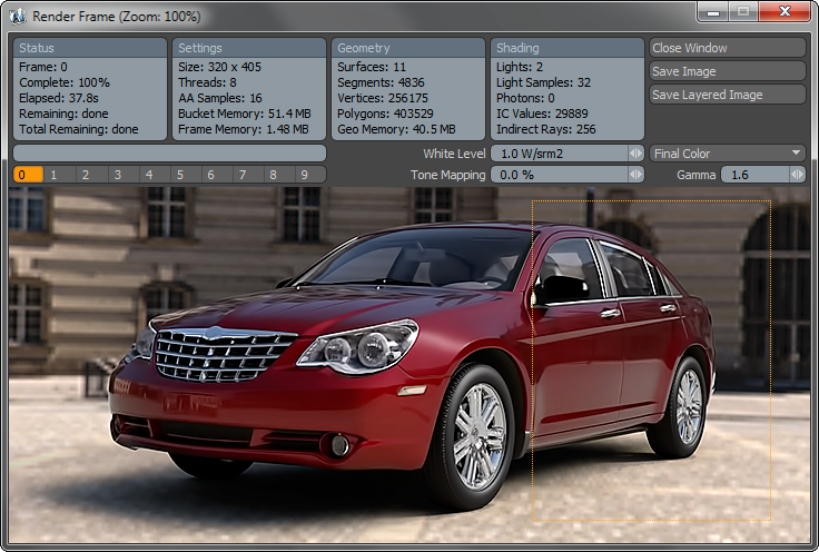
Drag out the box directly in the Render Display area using the LBM+click drag
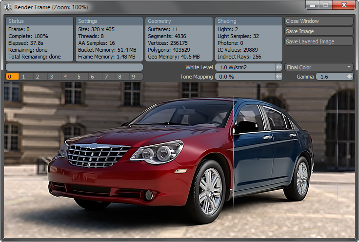
Now updates to the render display will be limited to the user defined region.
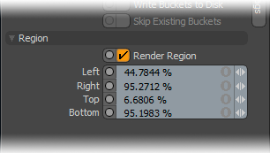
The Limited Region area is defined by a set of channels on the Render Item. You can adjust these numerically by selecting the Render Item and opening the Render Frame Properties form. To disable Limited Region rendering you can either click without dragging in the Render Window (as you would to drop a selection marquee in Photoshop) or you can click off the toggle on the Region tab of the Render Properties (shown below) disabling the region without losing the settings.